– by Ron Hayhurst
The majority of these tips have appeared in club newsletters over the years. Please note that you use them at your own risk as neither the Bristol Austin 7 Club nor the authors can be responsible for the results of trying to follow the instructions given.
Starter motor inspection and cleaning – Ron Hayhurst:
This article relates to the motor fitted to all post 1932 A7s. These are the ones to be found under the bonnet. Reluctance to crank the engine briskly on the self-starter is generally deemed to be the result of a low battery charge. However, if the problem persists when there is evidence that the battery is OK, then it is time to look elsewhere. First check the cable connections are clean and secure, but if still short of success, then it may be timely to make a thorough check of the starter. Isolate the battery and remove the starter.

The following operations are best carried out by mounting the starter in an engineer’s vice fitted with soft jaws. Remove the three screws holding the switch and check the condition of the copper contacts. These should be clean and smooth. If necessary dress up the contacts, which is most easily done with the one on the body of the starter as shown in the first picture. If the switch is in a bad state, a replacement can be obtained from the spares shed or a new one from A7 parts suppliers.

Having removed the dust cover it is likely that the area inside is covered in a copper “slime”!! This needs to be cleaned out. There are two brush connections. One goes to earth via the end cover and can be left undisturbed at this stage, but the other needs to be disconnected. With the unit stood on end in the vice, undo the two long screws holding the end cover and ease the cover off – see the second picture. This picture also shows the end cap that covers the screwdriver slot in the end of the armature. The body can now be lifted away from the armature and the armature set aside for later. The field windings are not connected to earth. Check that these windings are not shorting to the outer casing. It is a series-wound motor where the same current flows through the field and the armature to the earth point on the cover.

Carefully clean off the copper deposits on the end cover and reach down between the field windings on the main body. There are strong springs to hold the brushes in contact with the armature; check that these are in good order and then examine the brushes. Note/mark the way they are fitted before considering removal. New ones measure 15mm from the curved inboard face to the outer edge.

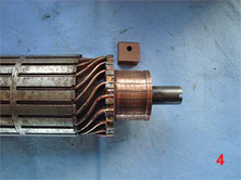
Wear down to 12.5mm must be about as much as can be tolerated. New ones are available. Clean up the armature looking first at the commutator. With any luck it will simply need a polish rather than a skim (as is often needed with dynamos). Fit the end cover and brushes on to the commutator and see that they make a good contact. If there is wear on the commutator, each brush must sit firmly on the commutator on reassembly. If new brushes are fitted it may be necessary to dress off the edge that would otherwise ride on the ridge of the unworn part of the commutator – see the alignment in the fourth picture. Having set aside the end-cover it is time to check out and clean the Bendix. Firmly clamp the armature in the vice, remove the split pin and unscrew the nut. Slide off all the parts making a note or picture of their location to help on reassembly.
Clean and dry all parts and reassemble with a smear of grease on the bush in the big casting. Check the condition of the spring clip on the Bendix gear and replace if in a poor state. New springs are available from our usual cherished parts suppliers. Tighten the nut and fit a new split pin. With this assembly mounted vertically in the vice – as when dismantling – slide the field body on to the armature. Apply a smear of grease to the end cover bush. With the brushes finger tight, ease them on to the commutator and ensure they nest down on to the worn part as described above before finally tightening. Fit the two long bolts and then inspect closely to again check the setting of the brushes. Place a small amount of grease in the cap and tap it on to the exposed screwdriver slot. Fit the switch back on and re-install in the car. Note: sometimes the caps are missing. Replacements can be found in the Bristol Austin 7 Club spares shed.
